
Content overview:
1 Principle of infrared signal transmitter
2 Correspondence between infrared signal transmitter and receiver
3 Infrared transmitter function implementation example
1 Principle of infrared signal transmitter
The first is the device itself that emits the infrared signal, which generally looks like this:
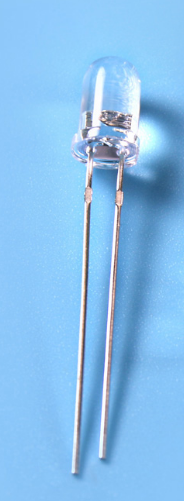
The diameter of the infrared diode in the picture is 3mm, and the other one is 5mm.
They are almost exactly the same as the light-emitting LEDs, so the longer pins are connected to the positive pole, and the other one is connected to the negative pole.
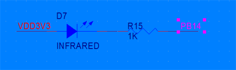
The simplest driving circuit is to add a 1k current limiting resistor to the positive street 3.3v, and then connect the negative electrode to the IO of the micro controller. As shown below:
2 Correspondence between infrared signal transmitter and receiver
Having said that, I need to correct a mistake in the next article with you.
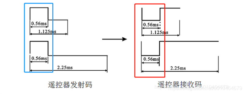
In the picture above, it is mentioned that the signal levels of the transmitter and the receiver are opposite. That is, the same as the content circled in the red and blue boxes in the above figure.
In fact, in the actual waveform, the blue part of the transmitter is not a simple high level of 0.56ms. Rather, it's a 0.56ms pwm wave of 38kHz.
The actual measured waveform is as follows:
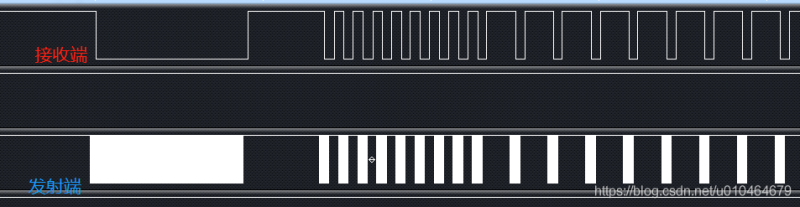
The waveform details of the wave color part of the transmitter in the figure are as follows:
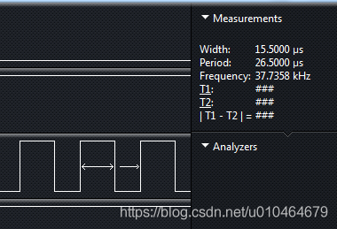
It can be seen that the frequency of this dense square wave is 38kHz.
Here is a summary: the correspondence between the transmitter and receiver of the infrared remote control:
When the transmitter outputs a 38kHz square wave, the receiver is low, otherwise the receiver is high
3 Infrared transmitter function implementation example
Now let's move on to programming practice.
According to the previous introduction, we know that to realize the function of an infrared remote control, we must first realize two basic functions:
1 38kHz square wave output
2 Control the 38kHz square wave to turn on and off at the desired time
The first is the 38kHz square wave output. We just use the pwm wave to generate it. Here, we need to use the pwm function of the timer. I am using the STM32L011F4P6 low-power chip here.
First use the code generation tool artifact cube to generate the code:
Initialization code:
Then there is the function of turning on or off the pwm wave according to the coding rules, which is implemented using timer interrupts, and then modify the length of time that the pwm wave is turned on or off by modifying the arrival time of the next interrupt:
There are still some details of the encoded data that will not be posted here. If you need more source code, you are welcome to leave a message, and I will provide you with the detailed code as soon as possible.
Post time: Feb-24-2022


